Computer Vision Rubik's Cube Solver
Computer Vision
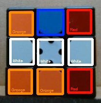
The system uses a webcam to get a picture of each of the six faces. From here, a script is written in python using OpenCV to detect the edges of each cube in the picture and then determine the color of each cube by using an HSV mask and creating contours for each color. An example of what the computer is "seeing" at this stage can be seen in the image to the right. After each cube color is determined for each face, a single string is made to define the current state of the Rubik's Cube. This works by assigning a direction (Up, Down, Left, Right, Front, Back) to each color and ensureing that the cube is in the robot in that orientation to solve.
Solving Algorithm
The solving algorithm for the cube is based on the Kociemba Two-Phase algorithm developed by Herbert Kociemba. For in-depth information on this algorithm, check out his website here. The basics of this algorithm involve using lookup tables of known solves for certain cube states and optimizing moves to get to one of these states. A half-turn method is used where each face can only be turned 180° for a solved cube. This allows a generation of a small enough subset of possible states that they can be put into lookup tables. The first phase of the solving searches solutions to get the scrambled cube to any of the saved states. It will continuously try and find solutions with lower and lower moves for 2 seconds, and once it can solve to any of the known states in the lookup table, the reverse of the moveset used to create that state is used to solve the cube. A string of moves in Rubik's Cube notation is then sent through usb serial communication to a microcontroller on the robot.
Robotic Solver and Hardware
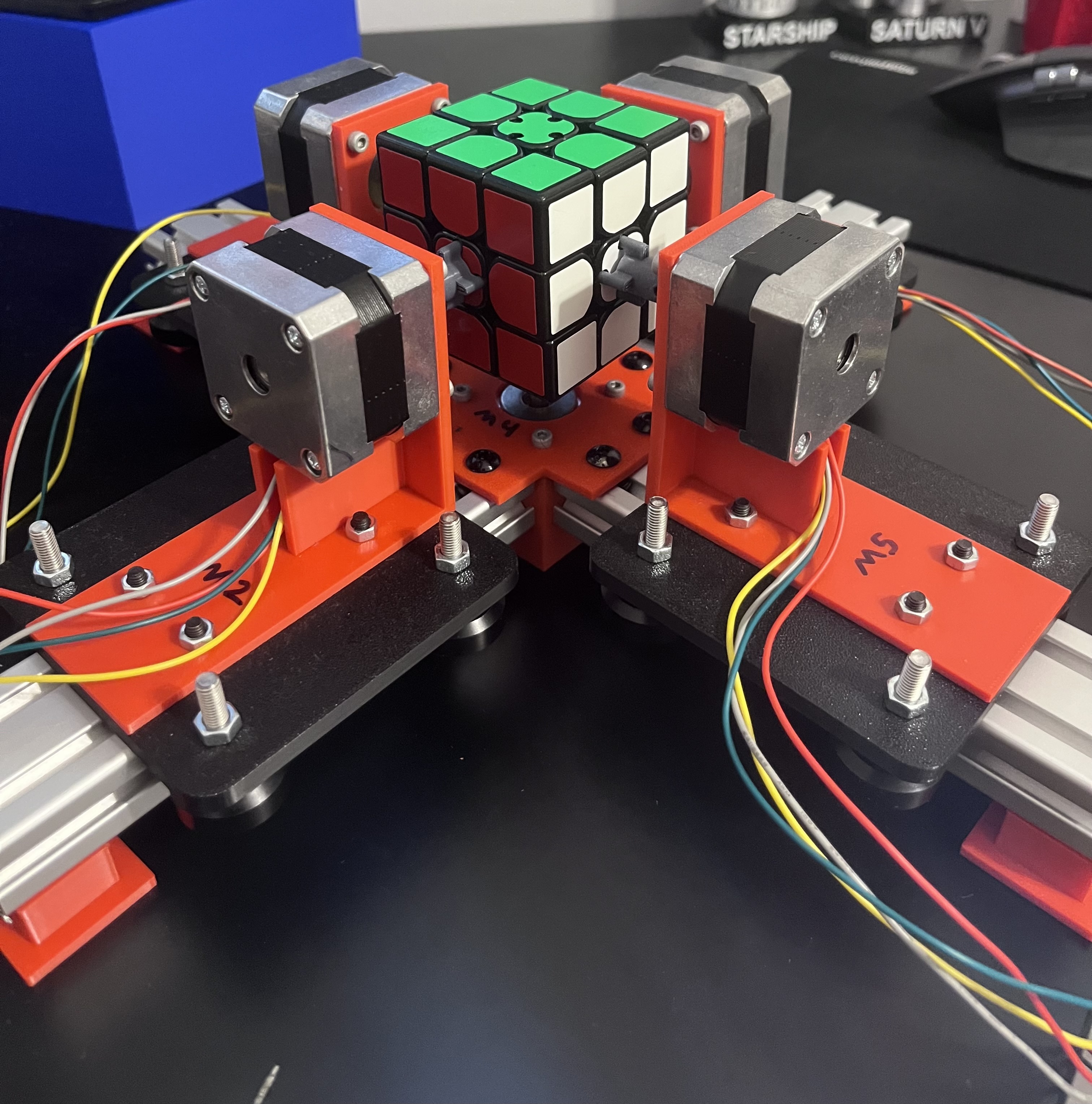
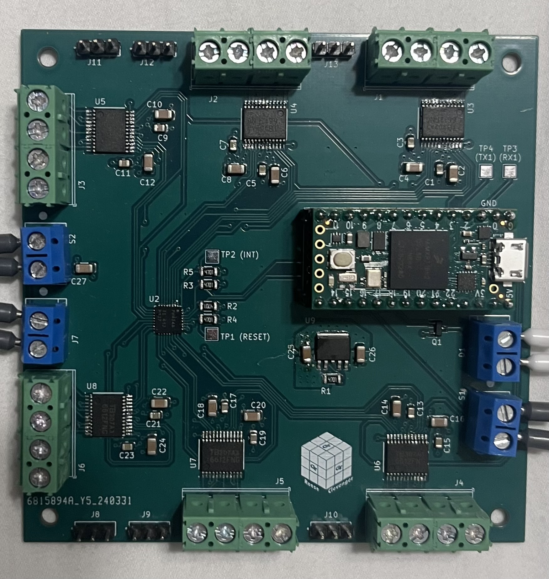
After the algorithm sends out a moveset to solve the cube, the robot will convert that string into a series of motor movements. For this, each face is associated with a motor. For example, if the string has a "L" for the left face, that might correspond to motor 2. Furthermore, a ' can be used (eg. L') to denote a counter-clockwise move for the motor. For the motors, each are 12V 1.8° stepper motors, each controlled by a TI dual H-bridge motor controller. The microcontroller used is a Teensy 4.0, and an I2C GPIO expander chip is used to give more I-O pins to the Teensy. The PCB shown is one that I designed in KiCAD to effectively manage connections and help keep a smaller package size. It was manufactured by JLCPCB and I did all the assembly by hand using resources at Georgia Tech.
Lessons Learned and Applications
Through this project, I was able to learn many new valuable skills, as well as refine some engineering practices. The main goal that I wanted to achieve in this project was to learn a bit about computer vision and how to implement that into an actual physical system rather than just on my screen. I ended up learning way more than I originally bargained for, and an unintended benefit was that I was able to strengthen my general python development skills as well along the way. Furthermore, this was my first time dabbling in serial communication, where I was able to learn not only about I2C communication, but research many different ones, including ethernet, USB, SPI, and a few others. I was able to learn a lot about how they work and benefits of using one versus the other. This was my second time designing a PCB from scratch, and while I was able to learn a lot about efficient PCB design, I really learned a lot from creating the schematic and learning about the different components I needed on the board and why. As far as mechanical design, motor controls is something I have always been fond of, so it is always nice to be able to learn and get better with that, and I was able to get good practice in designing a system that is not only functional, but also cohesive and easily modular to accomodate needed changes. In the future I hope to further progress this project by potentially adding an AI transformer for an enhanced color detection and upgrading certain designs to allow for faster and smoother turning of the cube.